Rhino3d is ideal and fast for designing urban scale models. Build basic house models with Extrusion and Boole tools. Learn how to fix bad DWG import geometry.
This is a short article about modeling house primitives in Rhino3D.
- Check Units and Grid
- 2D Curve: Polyline
- 2D Surface
- 3D Extrusion
- 3D Editing: Split Surface
- 3D Editing: Move Edges
- 3D Editing: Extrude Surfaces
- 3D Editing: Boole
- Troubleshooting Surface Generation
- Roundup and further resources
Check Units and Grid <
Before you start make sure to set your project to meter scale. (If it’s meant to be about architecture and you are outside the US.) The safest way to do this choose File – New and opt for Large Objects – Meters after starting Rhino3D.
It is also possible to automate this via a template, check this article of mine. Anyway your Rhino3D Options should present you with this on units:

And your grid should look like that:

If you want to work with Grid snapping you might want to downsize Snap spacing – it’s up to you and you can change it every time.
2D Curve: Polyline <
You start the modeling by drawing a 2D base contour. For a simple tiny house, this will most probably be a rectangle:

Draw a rectangle that has “normal” house measurements like 8 x 8 meters:

Of course, you can also use the Polyline tool if you need something more complex:


To keep things simple here, I will stick to my rectangle – it will be the base outline for my tiny house.
Keep in mind that for Rhino3D, every line is considered a curve. As such, it may be straight or bent. A sequence of lines may have sharp corners or be curvy over all – this is only a matter of curve degree. And any sequence of lines – representing a curve in Rhino terms – can be closed or not. For further information on curves, check Rhino3D’s manual.
2D Surface <
Now to extrude this rectangle into a closed solid you first need to turn it into a surface. (Because up to now it is only a bunch of edges.)
First of all, set your Perspective viewport to Shaded display:

Then choose Surface – Planar Curve:

Now you are prompted to select your rectangle and confirm with Enter (or faster: right-click). As a result you see the resulting surface:

If you do not succeed producing the surface your curve is either not planar or not closed. (In Rhino3D terms, a rectangle is a curve with degree 1.). To solve this check further down. For now, we proceed into 3D.
3D Extrusion <
Now let’s make this plane 3D by extruding it.
Select your surface. Mind you: not the edges, they are still there, too. By the way: In Rhino3D, in case you click on something ambiguous a window appears that allows you to choose what to select:

Again, select the surface. And: Be sure Gumball is active:

The Gumball is Rhino3D’s selection widget which allows a lot of things, among them extrude:

As you want to extrude in Z-direction, mouse-pick the little blue dot on the Gumball’s blue Z-axis and drag upwards. It’s a good idea to switch off Grid Snap for this.

You can either eyeball your extrusion or use an exact value. For this, abort with ESC and click on the little blue dot. A small input field appears. Here you may enter a dimension value:

Either way, you end up with a cubic solid:

3D Editing: Split Surface <
To add complexity to your “house” you want to subdivide your surfaces for further development. In order to produce a saddle roof for example you’ll need an additional edge in the middle of the top surface.
First of all be sure that you have some basic snap features enabled:

Then, choose Solid – Solid Edit Tools – Faces – Split Face:

Rhino3D prompts you to select the surface you want to split. Pick the top surface and right-click to confirm. Now Rhino3D prompts you to draw a line on that surface. For a start, draw it from midpoint to midpoint on opposite edges:

This should take two clicks. Again, right-click to confirm. Now you have added an additional edge dividing the top surface of your cube.
To better understand your model I suggest you switch off the isocurve display. Isocurves are the division lines that are shown on surfaces. In this case, they are not of much use and rather confusing. So, select the cube and in the Property panel uncheck Show surface isocurve:

If you are curious about isocurves, check Rhino3D’s online help. Anyway, now you see your new edge, ready for becoming a roof ridge.
3D Editing: Move Edges <
OK – that’s easy. Select the edge. As ist is part of a larger entity (the solid), you have to press CTRL-Shift while clicking:

Then grab the blue Gumball arrowhead (Z) and drag it upwards until you are satisfied. Again, if you single-click on the arrowhead instead you may again dial in a Z value for the move.
Now you’ve got a nice little house:

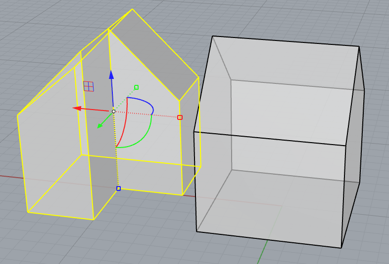
I found it boring to have only one house so I also took the other base contour and turned it into a house too.
(And I switched Diplay mode to Ghosted.)
3D Editing: Extrude Surfaces <
Moving Edges is one way to add complexity. Another strategy is to extrude partial surfaces. Let’s add some volume to the angular house on the left:
Let’s say we want to extrude the ground-floor-part of the rear gable wall. To do that we first have to split the gable wall surface. Choose the SplitFace command again. This time you don’t pick it from the Solid menu but write it like that into the command prompt:

You’ll notice that as soon as you start typing Rhino offers suitable commands. Pick SplitFace, select the gable wall surface, right-click to confirm. Then draw a new edge line like this:

Now CTRL-Shift-click the lower surface part and extrude it like so:

I used Grid Snap again to keep control over the movement.
Now to get rid of the new edge line dividing the two coplanar surfaces write merge – Rhino will offer you the MergeFace command:

Pick this one. You are prompted to select two faces – pick these two:

Rhino merges the two faces into one, thus getting rid of the dividing pseudo-edge:

3D Editing: Boole <
A third strategy for getting more complexity is adding or subtracting volume using Boole.

Let’s say you want a chimney coming out from one of the house’s roof. So change to Wireframe display and draw one using Box command, starting from the base XY-plane. You’ll see again that using Grid Snap will help you a lot with this schematic kind of modeling.
Then, use Boolean Union:

Select chimney and house (in Wireframe you’ll have to select edges to pick them) and right-click-confirm.
As you see, the two objects are united, the chimney part below the roof is gone:

Another way to utilize Boole is to subtract volume. Let’s say you want to cut some volume out of this house for a passage:

Do do that, simply draw an extra object to use it as cutter, using Box again:

Now choose BooleanDifference:

Follow Rhino’s prompts – first selct the volume to be substracted from. This would be the house. Right-click to confirm. Then select the cutter volume and confirm. The result:

Finally I just want to remind you that when drawing 2D base contours for an extrusion (via Box for example) you are free to choose any viewport. For example, here I start in the Front view outlining a base rectangle:

The extrusion part of the BOX command takes place in the Perspective viewport. Here I don’t care about exact length and Z-position:

Because the Z-position can be corrected in the Top viewport. Then, I used BooleanDifference again:

Of course, you can use more ready-made-geometry for cutters:

And there are also more Boole options like Intersect. Play around.
Troubleshooting Surface Generation <
While generating a surface from a closed curve (see above) you may get an error message:

This happens when the curve is either not closed or not planar.
A planar curve has points that have all the exact same height related to their base plane. This curve for example was drawn in the XY-Plane, so every point should have the same Z value:

In Front view you can see that this is not the case:

Luckily there’s a command to fix this easily. Write ProjectToCPlane:

After selecting the curve you should make sure that the crooked curve will be deleted after the action:

Now Rhino has flattened your curve down onto the base plane and you can proceed to build your surface:

The other reason why Rhino wouldn’t produce a surface inside a curve may be that the curve is not entirely closed. To fix this kind of problem, let’s look at a curve like that:

The curve looks closed but actually it isn’t:

This can happen when you don’t use snapping when drawing. Of course you may also get curves like that in imported CAAD files. Anyway, instead of putting your curve under the microscope to search for the bad corner just write CrvStart:

Then select the curve and right-click-confirm. Rhino marks the start point of the curve thus indicating where the gap is:

And this point is easy to spot, so there you are. Now, how to fix the gap? Either move the last curve point unto the start point (better turn on snapping for this).
Or choose Match, select the curve near the gap twice (near start, near end) and confirm. Rhino3D presents you some options:

In this article it’s all about degree-1-curves (= polylines), so the Position options should be appropriate. Press OK and you’re done.
An easy way to fix bad import geometry, this command.
For further information on closing curves via matching, check here.
Roundup and further Resources <
To do schematic modeling like this – adding up building dummies to an urban design model – is no big deal in Rhino3D. Basically, you have these options:
- Build geometry on 2D plans via 2D Curve, Surface, Extrusion
- Finetune geometry by splitting faces and moving edges
- Finetune geometry by splitting faces and extruding partial surfaces
- Finetune geometry by using Boolean tools
And using the Grid Snap (with correct units set) makes it all a lot easier.
For using correct units and grid snapping from the beginning read this article of mine.
I’ll write more articles on modeling in Rhino3D, so look ahead 😉
And here is how to start in Grasshopper.
© 2018 / Horst Sondermann / All Rights reserved


Leave a Reply
You must be logged in to post a comment.